概要
tone()は、ATmega328Pのタイマを使って、指定した周波数の方形波(矩形波)を指定したピンに生成します。PWM出力に利用するタイマと同じタイマ(タイマ/カウンタ2)を利用するので、デジタルピンの3番と11番へのPWMと干渉します。
タイマ関連のレジスタは、analogWrite()のページに記載しています。詳細はそちらを参照してください。
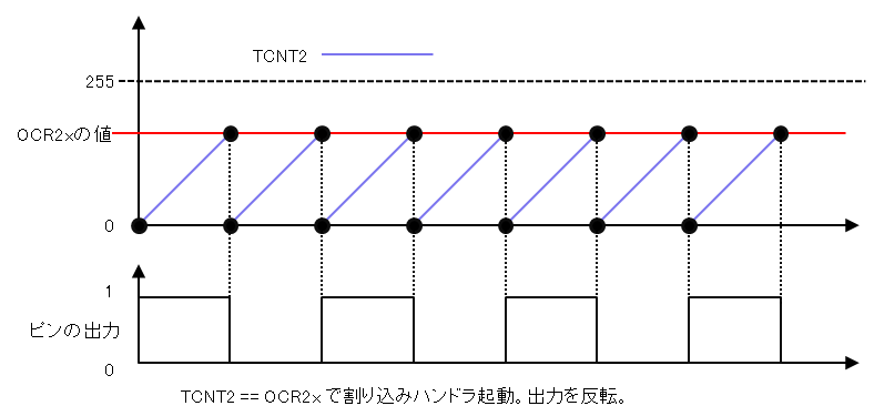
tone()で利用するタイマのモードは、CTC(Clear Timer on Compare)というモードです。タイマカウンタ(TCNTn)と比較レジスタ(OCRnx)との値を比較し、同じ値になったときにタイマカウンタを0に戻します。この際、割り込みを発生させ、割り込みハンドラの中でピン出力のオン・オフを切り替えます。
tone()のリファレンスは、こちらを参照してください。
ソースコード
tone()は、hardware/arduino/avr/cores/arduino/Tone.cpp に定義されています。以下に全ソースコードを示します。Arduino Unoの場合に適用される部分だけを抜粋しています。実際には#if によりさまざまなチップに対応しています。
1
2
3
4
5
6
7
8
9
10
11
12
13
14
15
16
17
18
19
20
21
22
23
24
25
26
27
28
29
30
31
32
33
34
35
36
37
38
39
40
41
42
43
44
45
46
47
48
49
50
51
52
53
54
55
56
57
58
59
60
61
62
63
64
65
66
67
68
69
70
71
72
73
74
75
76
77
78
79
80
81
82
83
84
85
86
87
88
89
90
91
92
93
94
95
96
97
98
99
100
101
102
103
104
105
106
107
108
109
110
111
112
113
114
115
116
117
118
119
120
121
122
123
124
125
126
127
128
|
volatile long timer0_toggle_count;
volatile uint8_t *timer0_pin_port;
volatile uint8_t timer0_pin_mask;
volatile long timer1_toggle_count;
volatile uint8_t *timer1_pin_port;
volatile uint8_t timer1_pin_mask;
volatile long timer2_toggle_count;
volatile uint8_t *timer2_pin_port;
volatile uint8_t timer2_pin_mask;
void tone(uint8_t _pin, unsigned int frequency, unsigned long duration)
{
uint8_t prescalarbits = 0b001;
long toggle_count = 0;
uint32_t ocr = 0;
int8_t _timer;
_timer = toneBegin(_pin);
if (_timer >= 0)
{
// Set the pinMode as OUTPUT
pinMode(_pin, OUTPUT);
// if we are using an 8 bit timer, scan through prescalars to find the best fit
if (_timer == 0 || _timer == 2)
{
ocr = F_CPU / frequency / 2 - 1;
prescalarbits = 0b001; // ck/1: same for both timers
if (ocr > 255)
{
ocr = F_CPU / frequency / 2 / 8 - 1;
prescalarbits = 0b010; // ck/8: same for both timers
if (_timer == 2 && ocr > 255)
{
ocr = F_CPU / frequency / 2 / 32 - 1;
prescalarbits = 0b011;
}
if (ocr > 255)
{
ocr = F_CPU / frequency / 2 / 64 - 1;
prescalarbits = _timer == 0 ? 0b011 : 0b100;
if (_timer == 2 && ocr > 255)
{
ocr = F_CPU / frequency / 2 / 128 - 1;
prescalarbits = 0b101;
}
if (ocr > 255)
{
ocr = F_CPU / frequency / 2 / 256 - 1;
prescalarbits = _timer == 0 ? 0b100 : 0b110;
if (ocr > 255)
{
// can't do any better than /1024
ocr = F_CPU / frequency / 2 / 1024 - 1;
prescalarbits = _timer == 0 ? 0b101 : 0b111;
}
}
}
}
if (_timer == 0)
{
TCCR0B = (TCCR0B & 0b11111000) | prescalarbits;
}
else
{
TCCR2B = (TCCR2B & 0b11111000) | prescalarbits;
}
}
else
{
// two choices for the 16 bit timers: ck/1 or ck/64
ocr = F_CPU / frequency / 2 - 1;
prescalarbits = 0b001;
if (ocr > 0xffff)
{
ocr = F_CPU / frequency / 2 / 64 - 1;
prescalarbits = 0b011;
}
if (_timer == 1)
{
TCCR1B = (TCCR1B & 0b11111000) | prescalarbits;
}
}
// Calculate the toggle count
if (duration > 0)
{
toggle_count = 2 * frequency * duration / 1000;
}
else
{
toggle_count = -1;
}
// Set the OCR for the given timer,
// set the toggle count,
// then turn on the interrupts
switch (_timer)
{
case 0:
OCR0A = ocr;
timer0_toggle_count = toggle_count;
bitWrite(TIMSK0, OCIE0A, 1);
break;
case 1:
OCR1A = ocr;
timer1_toggle_count = toggle_count;
bitWrite(TIMSK1, OCIE1A, 1);
break;
case 2:
OCR2A = ocr;
timer2_toggle_count = toggle_count;
bitWrite(TIMSK2, OCIE2A, 1);
break;
}
}
}
|
入力はpinとfrequency、duratoinで、それぞれuint8_t型、unsigned int型、unsigned long型の変数です。出力はありません。
まず、今回利用するATmega328Pのタイマを決定します。
14
15
16
17
18
19
|
uint8_t prescalarbits = 0b001;
long toggle_count = 0;
uint32_t ocr = 0;
int8_t _timer;
_timer = toneBegin(_pin);
|
toneBegin()は、ピンとタイマとの関連付けの管理と、タイマの設定を行います。現状の実装では、timer2_pin_portにタイマ出力に利用するピンに対応するポートが、timer2_pin_maskにポート内のビットが、それぞれ設定されます。これらは、最後に出てくる割り込みハンドラで利用します。
toneBegin()は、今回利用するタイマの番号を返します。現状返ってくるのは、2か-1です。2のときはタイマ/カウンタ2を利用します。タイマ/カウンタ2は、3番ピンと11番ピンのPWM出力でも利用するので干渉します。-1のときは、すでに他のピンでタイマが利用されているときです。
toneBegin()が0以上の値を返したら、tone()で利用するピンを、pinMode()で出力モードに設定します。toneBegin()が-1を返した場合は、何もせずにこの関数は終了します。
21
22
23
24
|
if (_timer >= 0)
{
// Set the pinMode as OUTPUT
pinMode(_pin, OUTPUT);
|
次に、タイマが0もしくは2の場合の処理が始まります。指定した周波数を出力するための設定値を求めます。
26
27
28
29
30
|
// if we are using an 8 bit timer, scan through prescalars to find the best fit
if (_timer == 0 || _timer == 2)
{
ocr = F_CPU / frequency / 2 - 1;
prescalarbits = 0b001; // ck/1: same for both timers
|
ocrは、比較レジスタに設定する値で、タイマの周波数を決定します。タイマ/カウンタ0と2をCTCモードで利用する場合の周波数(f)は以下のように決まります。
f = クロック周波数 / ( 2 * 分周比 * ( 1 + 比較レジスタの値))
今回は、周波数を入力に、比較レジスタの値を決める必要があるので、この式を変形すると以下のようになります。
比較レジスタの値(ocr) = クロック周波数 / ( 2 * 分周比 * f ) - 1
tone()では、まず、分周比を1として計算しています。
分周比の設定に利用する値をprescalarbitsに設定します。分周比1のときは、TCCR0BもしくはTCCR2Bの下位3ビットの値を0b001に設定します。
タイマ/カウンタ0と2の比較レジスタは8ビットなので、0から255までの値しか設定できません。このため、255を超えた場合には、再計算が必要です。その場合は、分周比を2にして、比較レジスタの値を再計算します。分周比が2の場合は、TCCR0BもしくはTCCR2Bの下位3ビットの値を0b010に設定します。
31
32
33
34
|
if (ocr > 255)
{
ocr = F_CPU / frequency / 2 / 8 - 1;
prescalarbits = 0b010; // ck/8: same for both timers
|
以下、比較レジスタに設定する値が255を超えないように、再計算を繰り返します。
36
37
38
39
40
41
42
43
44
45
46
47
48
49
50
51
52
53
54
55
56
57
58
59
60
61
62
63
64
65
|
if (_timer == 2 && ocr > 255)
{
ocr = F_CPU / frequency / 2 / 32 - 1;
prescalarbits = 0b011;
}
if (ocr > 255)
{
ocr = F_CPU / frequency / 2 / 64 - 1;
prescalarbits = _timer == 0 ? 0b011 : 0b100;
if (_timer == 2 && ocr > 255)
{
ocr = F_CPU / frequency / 2 / 128 - 1;
prescalarbits = 0b101;
}
if (ocr > 255)
{
ocr = F_CPU / frequency / 2 / 256 - 1;
prescalarbits = _timer == 0 ? 0b100 : 0b110;
if (ocr > 255)
{
// can't do any better than /1024
ocr = F_CPU / frequency / 2 / 1024 - 1;
prescalarbits = _timer == 0 ? 0b101 : 0b111;
}
}
}
}
|
タイマ/カウンタ0とタイマ/カウンタ2とでは、設定できる分周比に差があります。タイマ/カウンタ0は、分周比32が設定できませんが、タイマ/カウンタ2では設定可能です。また、タイマ/カウンタ0と2とで設定する値に差があるので、タイマ/カウンタによって設定する値を変更しています。
タイマ/カウンタ0と2とで設定できる分周比の最大値は1024です。それ以上の設定はできません。分周比が1024で比較レジスタの値が255のとき、周波数は、30.5Hzです。また、分周比が1で比較レジスタの値が0のとき、周波数は8MHzです。つまり、tone()で出せる周波数は、30.5Hzから8MHzになります。ただし、tone()の引数に設定するfrequencyは、unsigned int型なので、実際には65535Hzが最大値となります。人間の耳で聞こえる周波数は、20Hzから20kHzといわれているので、十分ではないでしょうか。
次に、タイマ/カウンタを設定を行うレジスタに値を設定します。タイマ/カウンタ0ではTCCR0B、2では、TCCR2Bです。
67
68
69
70
71
72
73
74
|
if (_timer == 0)
{
TCCR0B = (TCCR0B & 0b11111000) | prescalarbits;
}
else
{
TCCR2B = (TCCR2B & 0b11111000) | prescalarbits;
}
|
次は、toneBegin()が0と2以外を返したときですが、現在の実装ではこの場合はありません。16ビットタイマを利用する想定のコードのようです。
76
77
78
79
80
81
82
83
84
85
86
87
88
89
90
91
|
else
{
// two choices for the 16 bit timers: ck/1 or ck/64
ocr = F_CPU / frequency / 2 - 1;
prescalarbits = 0b001;
if (ocr > 0xffff)
{
ocr = F_CPU / frequency / 2 / 64 - 1;
prescalarbits = 0b011;
}
if (_timer == 1)
{
TCCR1B = (TCCR1B & 0b11111000) | prescalarbits;
}
|
tone()で方形波を出力する時間を設定します。出力する時間をピンのオン・オフの回数に変換して、toggle_countに設定します。時間に0を指定したとき(省略したときも含みます)は、-1を設定しています。この場合は、noTone()で明示的に出力を止めるまで出力され続けます。
94
95
96
97
98
99
100
101
102
|
// Calculate the toggle count
if (duration > 0)
{
toggle_count = 2 * frequency * duration / 1000;
}
else
{
toggle_count = -1;
}
|
次に、レジスタの設定と割り込みベクタの中で参照するための変数を設定します。
104
105
106
107
108
109
110
111
112
113
114
115
116
117
118
119
120
121
122
123
124
125
126
|
// Set the OCR for the given timer,
// set the toggle count,
// then turn on the interrupts
switch (_timer)
{
case 0:
OCR0A = ocr;
timer0_toggle_count = toggle_count;
bitWrite(TIMSK0, OCIE0A, 1);
break;
case 1:
OCR1A = ocr;
timer1_toggle_count = toggle_count;
bitWrite(TIMSK1, OCIE1A, 1);
break;
case 2:
OCR2A = ocr;
timer2_toggle_count = toggle_count;
bitWrite(TIMSK2, OCIE2A, 1);
break;
}
|
現状_timerは2しかとらないので、OCR2AとTIMSK2の設定を行います。
OCR2Aは比較レジスタで、1クロックごとに加算されるTCNT2とOCR2Aの値が一致すると、割り込みを発生させ、TCNT2は0にリセットされます。
TIMSK2は割り込みマスクを制御するレジスタで、OCIE2Aを設定すると、TCNT2とOCR2Aの値が一致したときの割り込みを許可します。
bitWrite()は、第1引数で指定した変数の、第2引数で指定したビット(一番右が第0ビット)を、第3引数で指定した値に設定するマクロです。
timer2_toggle_countにtoggle_countを代入します。
ここまでが、tone()関数ですが、タイマ/カウンタの設定を行うだけで、ピンへの出力は行っていません。ピンへの出力は、TIMER2_COMPA_vectという、タイマ/カウンタ2の割り込みハンドラの中で行います。この割り込みハンドラは、タイマ/カウンタ(TCNT2)と比較レジスタ(OCR2A)が同じ値になったときに起動されます。
バージョン
Arduino AVR Boards 1.8.6
最終更新日
March 21, 2023