Abstract
Digital input and output of Arduino(ATmega328P) are performed by reading or writing from or to ports which are registers of the chip.
The pinMode() is a function to configure the port as an input or an output. Actually it is to configure DDR(Data Direction Register) which corresponds to the pin that is specified by the argment to the pinMode(). If the bit of corresponding DDR is 0, the pin is configured as an input. If the bit of DDR is 1, the pin is configured as an output.
ATmega328P has an ability to use internal pullup registers. Until Arduino 1.0, we needed to configure the pullup resister with two steps. First, make a digital pin INPUT with pinMode(), then, output HIGH to the pin with digitalWrite(). From Arduino 1.0.1, the software is modified to configure the pullup resister with pinMode() only.
DDR is a generic name and ATmega328P has three DDRs which are called DDRB, DDRC and DDRD. The relation of pins of Arduino and DDRs is shown below. The Axs are analog pins and the Dxs are digital pins. For example, if the fifth bit of DDRB is 1, the digital pin 13 is configured as output. The initial values of DDRs are zero, which mean INPUT.
ATmega328P also has three registers that determine the value of digital pins, PORTB, PORTC and PORTD. Each bit of PORTs and Arduino digital pins are shown below.The Axs are analog pins and the Dxs are digital pins. The initial values of PORTs are zero, which is LOW.
| DDRB/PORTB | ||||||||
|---|---|---|---|---|---|---|---|---|
| Bit | 7 | 6 | 5 | 4 | 3 | 2 | 1 | 0 |
| Pin | - | - | D13 | D12 | D11 | D10 | D9 | D8 |
| DDRC/PORTC | ||||||||
| Bit | 7 | 6 | 5 | 4 | 3 | 2 | 1 | 0 |
| Pin | - | - | A5 | A4 | A3 | A2 | A1 | A0 |
| DDRD/PORTD | ||||||||
| Bit | 7 | 6 | 5 | 4 | 3 | 2 | 1 | 0 |
| Pin | D7 | D6 | D5 | D4 | D3 | D2 | D1 | D0 |
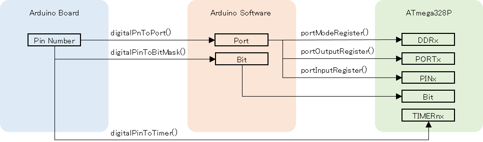
The rough diagram to convert Arduino pin number to ATmega328P register is shown below.
The pinMode() is a function that dose
- determine which bit of DDR to set
- set the bit to 0(INPUT) or 1(OUTPUT)
To enable the internal pullup resister, first make the pin input then output HIGH to the pin.
Source Code
The pinMode() is defined in hardware/arduino/avr/cores/arduino/wiring_digital.c as below.
|
|
The input arguments are pin and mode. The type of the variables are both uint8_t.
First calculate the bit mask, which bit in the PORTx, of the pin.
|
|
The digitalPinToBitMask() is a macro defined in hardware/arduino/avr/cores/arduino/Arduino.h. It returns a value with a corresponding bit, shown in the table above, of DDR set to 1. For example, if the pin is 13, the value 0b00100000 is returned. It means the fifth bit of PORTB.
The digitalPinToPort() is also a macro defined in hardware/arduino/avr/cores/arduino/Arduino.h. It returns the PORT corresponds to the pin. If the pin is from 0 to 7, it returns PD, from 8 to 13 it returns PB, from 14(A0) to 19(A5) it returns PC.
If the port is NOT_A_PIN, the function returns without doing anything more.
|
|
In case of Arduino Uno, if the input value is correct/valid, digitalPinToPort() dose not return NOT_A_PIN. If the input value is incorrect/invalid, it refers to the out of range of an array, and its behavior is undefined. This means we must not give incorrect input parameters.
Then, convert the port to a registers.
|
|
The portModeRegister() is a macro defined in hardware/arduino/avr/cores/arduino/Arduino.h. It converts the port to the address of DDR. It returns DDRB, DDRC or DDRD according to the port. If the port is PB, it returns DDRB.
The portOutputRegister() is a macro defined in hardware/arduino/cores/arduino/Arduino.h. It converts the port to PORT. It returns PORTB, PORTC or PORTD. If the port is PB, it returns PORTB.
At the last, the pinMode() dose the real thing.
- When the mode is INPUT
- make the bit of DDR to 0, and the bit of PORT to 0
- When the mode is INPUT_PULLUP
- make the bit of DDR to 0, and the bit of PORT to 1
- When the mode is OUTPUT(actually the mode is not INPUT or INPUT_PULLUP)
- make the bit of DDR to 1
|
|
The SREG is a status register which holds interrupt enable flag, carry flag and so on. Before changing the pin mode, SREG is stored to oldSREG. Then disable interrupts using cli().
To make the specified bit of a variable 0, invert the bit and calculate a logical(bitwise) AND. For example, if the pin is 13, the bit is 0b00100000, so ~bit is 0b11011111. Calculating this logical(bitwise) AND with this value and DDR, the bit which corresponds to the pin 13 would become 0.
To make the specified bit of a variable 1, calculate the logical(bitwise) OR.
Then it puts the oldREG back to REG.
Version
Arduino AVR Boards 1.8.6
Last Update
March 21, 2023