The tone() generates square wave with specified frequency using timer of ATmega328P to the specified pin. This uses the timer/counter2, which is also used to generate PWM wave, it interferes the digital pin 3 and 11.
The registers related to timer is written in analogWrite().
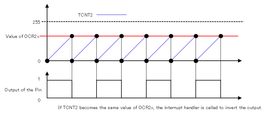
The timer mode which is used by tone() is called CTC(Clear Timer on Compare). If the values of timer counter(TCNTn) and compare register(OCRnx) become the same, an interrupt is raised and an interrupt handler is called to invert the output of the pin.
Source Code
The tone() is defined in hardware/arduino/avr/cores/arduino/Tone.cpp as below. Only the source code for Arduino UNO is quoted. The original source code supports many chips using #if’s.
volatilelongtimer0_toggle_count;volatileuint8_t*timer0_pin_port;volatileuint8_ttimer0_pin_mask;volatilelongtimer1_toggle_count;volatileuint8_t*timer1_pin_port;volatileuint8_ttimer1_pin_mask;volatilelongtimer2_toggle_count;volatileuint8_t*timer2_pin_port;volatileuint8_ttimer2_pin_mask;voidtone(uint8_t_pin,unsignedintfrequency,unsignedlongduration){uint8_tprescalarbits=0b001;longtoggle_count=0;uint32_tocr=0;int8_t_timer;_timer=toneBegin(_pin);if(_timer>=0){// Set the pinMode as OUTPUT
pinMode(_pin,OUTPUT);// if we are using an 8 bit timer, scan through prescalars to find the best fit
if(_timer==0||_timer==2){ocr=F_CPU/frequency/2-1;prescalarbits=0b001;// ck/1: same for both timers
if(ocr>255){ocr=F_CPU/frequency/2/8-1;prescalarbits=0b010;// ck/8: same for both timers
if(_timer==2&&ocr>255){ocr=F_CPU/frequency/2/32-1;prescalarbits=0b011;}if(ocr>255){ocr=F_CPU/frequency/2/64-1;prescalarbits=_timer==0?0b011:0b100;if(_timer==2&&ocr>255){ocr=F_CPU/frequency/2/128-1;prescalarbits=0b101;}if(ocr>255){ocr=F_CPU/frequency/2/256-1;prescalarbits=_timer==0?0b100:0b110;if(ocr>255){// can't do any better than /1024
ocr=F_CPU/frequency/2/1024-1;prescalarbits=_timer==0?0b101:0b111;}}}}if(_timer==0){TCCR0B=(TCCR0B&0b11111000)|prescalarbits;}else{TCCR2B=(TCCR2B&0b11111000)|prescalarbits;}}else{// two choices for the 16 bit timers: ck/1 or ck/64
ocr=F_CPU/frequency/2-1;prescalarbits=0b001;if(ocr>0xffff){ocr=F_CPU/frequency/2/64-1;prescalarbits=0b011;}if(_timer==1){TCCR1B=(TCCR1B&0b11111000)|prescalarbits;}}// Calculate the toggle count
if(duration>0){toggle_count=2*frequency*duration/1000;}else{toggle_count=-1;}// Set the OCR for the given timer,
// set the toggle count,
// then turn on the interrupts
switch(_timer){case0:OCR0A=ocr;timer0_toggle_count=toggle_count;bitWrite(TIMSK0,OCIE0A,1);break;case1:OCR1A=ocr;timer1_toggle_count=toggle_count;bitWrite(TIMSK1,OCIE1A,1);break;case2:OCR2A=ocr;timer2_toggle_count=toggle_count;bitWrite(TIMSK2,OCIE2A,1);break;}}}
The inputs are pin, frequency and duration and the types are uint8_t, unsigned int and unsigned long respectively. It has no output.
The toneBegin() manages the relation of pin and timer, and sets ther timer. In the current implementation, timer2_pin port is used to set timer output port and timer2_pin_mask is used to set timer output bit. These variables are used in an intterrupt handler.
The toneBegin() returns timer number to use. Currently it returns 2 or -1. If the return value is 2, the timer/counter2 is used. The timer/counter2 is also used by PWM output to digital pins 3 and 11, so it interferes. If the return is -1, the timer is already used by another pin.
If the toneBegin() returns a value which is greater than 0, it sets the pin to output mode by using pinMode(). If the toneBegin() returns -1, this function ends.
21
22
23
24
if(_timer>=0){// Set the pinMode as OUTPUT
pinMode(_pin,OUTPUT);
If the timer is 0 or 2, calculates the setting values to output the specified frequency.
26
27
28
29
30
// if we are using an 8 bit timer, scan through prescalars to find the best fit
if(_timer==0||_timer==2){ocr=F_CPU/frequency/2-1;prescalarbits=0b001;// ck/1: same for both timers
The ocr is a value to be set to compare register and it determines timer frequency. The frequency which is generated by timer/counter0 or 2 with CTC mode is determined as below.
f = clock frequency / ( 2 * division ratio * ( 1 + value of compare register))
This time the value of compare register must be determined from frequency, the formula becomes like this.
value of compare register(ocr) = clock frequency / ( 2 * division ratio * f ) - 1
In the tone(), first the division ratio is 1.
The value which is used to determine division ratio is set to prescalarbits. When the division ratio is 1, it sets the lower 3 bits of TCCR0B or TCCR2B to 0b001.
Because the timer/counter0 and 2 is 8 bits width, 0 to 255 can be set. When the value exceeds 255, recalculation is needed. In this case, the division ratio is set to 2 and calculates the compare register value again. When the division ratio is 2, it sets the lower 3 bits of TCCR0B or TCCR2B to 0b010.
31
32
33
34
if(ocr>255){ocr=F_CPU/frequency/2/8-1;prescalarbits=0b010;// ck/8: same for both timers
It repeats calculation so that the value of compare register dose not exceed 255.
if(_timer==2&&ocr>255){ocr=F_CPU/frequency/2/32-1;prescalarbits=0b011;}if(ocr>255){ocr=F_CPU/frequency/2/64-1;prescalarbits=_timer==0?0b011:0b100;if(_timer==2&&ocr>255){ocr=F_CPU/frequency/2/128-1;prescalarbits=0b101;}if(ocr>255){ocr=F_CPU/frequency/2/256-1;prescalarbits=_timer==0?0b100:0b110;if(ocr>255){// can't do any better than /1024
ocr=F_CPU/frequency/2/1024-1;prescalarbits=_timer==0?0b101:0b111;}}}}
Timer/counter0 and timer/counter2 has different feature. The timer/counter0 cannot set 32 for division ratio, but the timer/counter2 can. So the code for each timer/counter is needed.
The largest value which can be set as division ratio is 1024. If the division ratio is 1024 and the value of compare register is 255, the frequency is 30.5Hz. If the division ratio is 1 and the value of compare register is 0, the frequency is 8MHz. This means tone() can generate frequency from 30.5Hz to 8MHz. But the type of the frequency passed to tone() is unsigned int, the maximum frequency is suppressed to 65535Hz.
Next it sets the value to timer/counter related register. The regisger used is TCCR0B for timer/counter0, TCCR2B for timer/counter2.
Next code are for when the toneBegin() returns other than 0 or 2, but in the current implementation it dose not happen. It looks like codes to use 16-bit timer.
76
77
78
79
80
81
82
83
84
85
86
87
88
89
90
91
else{// two choices for the 16 bit timers: ck/1 or ck/64
ocr=F_CPU/frequency/2-1;prescalarbits=0b001;if(ocr>0xffff){ocr=F_CPU/frequency/2/64-1;prescalarbits=0b011;}if(_timer==1){TCCR1B=(TCCR1B&0b11111000)|prescalarbits;}
tone() sets the duration to output square wave. The duration is converted to the number of times to invert the output, then set to toggle_count. When the duration is 0 , including omission, -1 is set. In this case the tone is output until the noTone() is called.
 94
 95
 96
 97
 98
 99
100
101
102
// Calculate the toggle count
if(duration>0){toggle_count=2*frequency*duration/1000;}else{toggle_count=-1;}
Sets registers and a variable which is referred in interrupt handler.
// Set the OCR for the given timer,
// set the toggle count,
// then turn on the interrupts
switch(_timer){case0:OCR0A=ocr;timer0_toggle_count=toggle_count;bitWrite(TIMSK0,OCIE0A,1);break;case1:OCR1A=ocr;timer1_toggle_count=toggle_count;bitWrite(TIMSK1,OCIE1A,1);break;case2:OCR2A=ocr;timer2_toggle_count=toggle_count;bitWrite(TIMSK2,OCIE2A,1);break;}
In the current implementation, _timer is fixed to 2, OCR2A and TIMSK2 are set.
The OCR2A is a compare register, it is incremented at every clock. When the TCNT2 and OCR2A becomes the same value, an interrupt would occur and TCNT2 is reset to 0.
TIMSK2 is controls interrupt mask. When OCIE2A is set, the interrupt when TCNT2 and OCR2A becomes the same value is enabled.
The bitWrite() is a macro to set the second argument bit of the first argument variable to the value of the third argument.
The toggle_count is set to timer2_toggle_count.
Here ends the tone(), but it sets only timer/counter but dose not output to pins. The output to pins is processed in the interrupt handler named TIMER2_COMPA_vect. This handler is called when timer/counter2(TCNT2) and compare register(OCR2A) becomes the same value.